Diamond Core Drilling
The design simplicity of core drilling tools means that, apart from normal wear patterns, there is little to go wrong, provided the correct bit is chosen for the material to be cut.
Please note the following most common faults and their most obvious causes. If these first measures do not correct the fault, please stop drilling and call the Diaquip Technical Services Dept. for advice on 0161 4060609 or e-mail technical@diaquip.co.uk
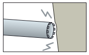 A. The Core Drill Fails to Cut
Possible Causes
1. Machine is unstable or insecurely fixed.
2. Motor is of insufficient power.
3. The Core Drill is not of the right diamond specification for the material to be cut.
4. Diamond segments have become ‘glazed’.
5. Excessive coolant, causing the drill to slide or aquaplane.
6. Insufficient downward weight or pressure on the drill.
7. Excessive drilling speed.
8. Excessive play in the spindle or carriage guides.
Corrective Measures
1. Ensure machine is firmly anchored and stable.
2. Ensure motor of correct power is fitted.
3. Fit Core Drill of correct diamond specification.
4. Run the drill briefly on abrasive material to open-up the diamond surface.
5. Adjust coolant flow and ensure even distribution.
6. Increase downward pressure and apply this evenly.
7. Reduce drilling speed.
8. Ensure a snug fit between spindle and drill. Tighten carriage guides.
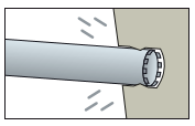 B. The Core Drill Jams in the Hole
Possible Causes
1. The material to be cut is too hard for the Core Drill or has hard patches which exceed the diamond specification.
2. Rubble or debris has filled the drilling hole (NB this may include a segment which has broken off).
3. The Core Drill does not have sufficient side clearance for the segments to operate effectively.
Corrective Measures
1. Replace Core Drill with one suitable for the toughest material likely to be encountered.
2. Ensure adequate irrigation of the drill hole and flush out completely before recommencing drilling
3. Check side clearance (this should be adequate, but not excessive). If necessary, replace Core Drill.
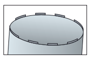 C. Excessive Segment Wear
Possible Causes
1. Rotational speed too low.
2. Material to be cut is too abrasive for the diamond specification or has unexpected abrasive patches.
3. Motor power is too high.
4. Instability of the machine or excessive play in the spindle or carriage guides.
5. Cooling system is not working adequately.
Corrective Measures
1. Increase speed.
2. Replace Core Drill with one suitable for the abrasive material likely to be encountered.
3. Fit a motor of the correct specification.
4. Ensure machine is firmly anchored and stable. Ensure a snug fit between spindle and drill. Tighten carriage guides.
5. Overhaul cooling system and adjust flow to correct levels.
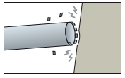 D. Segments Break Off
Possible Causes
1. Excessive heat due to insufficient cooling.
2. Segments have become damaged by unremoved debris.
3. Segments have insufficient lateral operating space.
4. Excessive speed at start-up.
5. Core Drill has been dropped or damaged in transit.
Corrective Measures
1. Ensure that the water flow provides the correct level of cooling for the operating speed. Repair or replace segments.
2. Flush the drill hole clear of debris and increase water flow to ensure that problem does not recur. Remember that broken segments may form part of the debris and ensure that these are accounted for and removed, as otherwise these may cause substantial damage. Repair or replace segments.
3. Check side clearance (this should be adequate, but not excessive). If necessary, replace Core Drill.
4. Reduce and graduate start-up speed.
5. Inspect closely before use and after any transportation. Damage may be in the form of hairline cracks and segments which have been torn off, so close inspection is necessary. Repair or replace segments.
E. Excessive Tube Wear
Possible Causes
1. Machine is unstable or operating at the wrong angle.
2. Too much play in the spindle or carriage guides.
3. The Core Drill has become damaged and is operating out of true.
4. The Core Drill is not properly fitted.
5. Debris is obstructing the tool.
Corrective Measures
1. Ensure machine is firmly anchored and stable.
2. Ensure a snug fit between spindle and Core Drill. Check rollers and bearings. Tighten carriage guides.
3. Repair any warped or damaged parts. Ensure that Core Drill is running true before continuing.
4. Check that the Core Drill is correctly aligned and centred on the spindle.
5. Flush the debris from within the drill hole and ensure correct water flow is maintained subsequently.
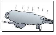 F. Machine and Motor Problems
Possible Causes
1. Motor is underpowered.
2. Machine is unstable or positioned at an angle.
3. Cooling system problems.
4. Drill Motor is not properly fitted to the machine, causing excessive vibration.
5. Carriage guides and spindle fitting are too loose.
Corrective Measures
1. Replace with a motor of the correct power.
2. Ensure machine is firmly anchored and stable.
3. Overhaul the cooling system, ensuring correct and even flow for the work being undertaken.
4. Check all the moving parts on the machine, especially spindle, bearings, rollers and carriage guides. Ensure that parts are centred and operating freely but without excessive play.
5. As 4) above.
Diamond Wire Sawing
Two of the main problems associated with wire sawing are ‘flatspotting’ (uneven wearing of the diamond beads) and wire breakage / connector pull-out. Attention paid to the procedures outlined below will minimise the risk of these problems occurring.
Please note the following most common faults and their most obvious causes. If these first measures do not correct the fault, please stop sawing and call the Diaquip Technical Services Dept. for advice on 0161 4060609 or e-mail technical@diaquip.co.uk
A. Flatspotting (one-sided wear of Diamond Beads)
Flatspotting can largely be prevented and/or cured by changing the amount of twist in the wire after every cut, i.e. changing the position of the diamond beads in relation to each other, as viewed by looking at the end of wire in cross-section.
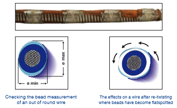 If flatspotting is beginning to occur, re-twisting the wire effectively changes the position of the beads and makes the wire round again in cross-section. This is only likely to be an effective correction provided that the wire has not gone beyond 0.4mm out of round.
As a rule a wire should start with 1 twist per metre, adding 30% of twist after each large cut up to a maximum 2-3 twists per metre. If there is still life left in the wire at this point, start to decrease the number of cuts by 30% : thus, over a 10 metre length of wire, the twist progression would be 10 > 13 > 17 > 22, thereafter decreasing by 30%, 17 > 13 > 10.
B. Connector Pull Out

These problems can be greatly reduced by paying attention to the following:
- Ensure the end of the wire to be crimped is cleanly and squarely cut;
- Clean all plastic or rubber residue off the wire where the connector is to be mounted;
- Use the correct hydraulic press – minimum of 5T for low pressure, pneumatic-feed machines and 8T for higher power machines;
- Use the correct pressing tool inserts, different for different types of connectors. Consult the table of recommendations on Page 8;
- Ensure that over-tensioning of wire is avoided by having the correct feed pressure control;
- Check that all sharp corners of the workpiece have been radiused off prior to the commencement of wire sawing and that the workpiece is wedged securely in position as cutting progresses, so that the wire is not trapped.
C. Wire Breakage

Wire breakage and connector pull-out are often confused as being the same thing, but can have quite separate causes:
Wire breakage can also be caused by inattention to some of the connection pull-out warnings, but, in addition, one of the most common causes of failure is a breakage immediately adjacent to the connector.
This breakage is due to the frequency of forward and backward deflection of the wire by the Wire Saw’s pulleys, which will eventually fatigue the wire at its weakest point due to the lack of flexibility near to the connector joint. The length of time until the crimped wire breaks at this point depends on various factors, but in general a shorter connector, or ideally a flexible one, will have a longer life.
On smaller cuts, the connector will often last until the job is completed, but on larger ones it is advisable for the operator to monitor the length of time before a fatigue breakage occurs and, subsequently, to stop the wire and renew the connector within a safe margin of time before a further breakage is expected. This is extremely important, as when a breakage does occur, more damage is likely to be caused by the ruptured wire hitting sharp surfaces at high speed, which can in turn lead to further breakages.
In addition to the above, sawing will run more smoothly if narrow arcs of contact between wire and cut-piece can be avoided, using deflection or satellite pulleys where appropriate to do so. Instructions on connection assembly should also be followed closely. At all times vibrations on the wire during sawing should be kept to a minimum, by watching the process closely and keeping within the machine’s operating parameters.
Wall Sawing and Floor Sawing
Good product selection, regular observation and maintenance are the keys to obtaining maximum life from wall and floor saw blades. The following notes should assist you to obtain the maximum life expectancy from blades and help keep within Health and Safety guidelines at all times.
Blades should be checked regularly for cracks, discolouration and signs of overheating or undercutting. All these faults could lead to segment loss, after which it is unsafe to use the blade further.
As most problems occur as a result of incorrect blade choice, inappropriate usage and faults with the equipment (e.g.motor, machine stability and water/coolant supply), particular attention should be paid to these aspects and to the manufacturer’s instructions before sawing commences. When problems occur during usage, the following aspects should be checked as the most obvious causes and solutions, and the machine stopped to avoid further damage.
If these immediate ‘first aid’ measures do not solve the problem, please call the Diaquip Technical Services Dept. for further advice. Do not use the machine again until this is obtained.
1. Diamond Blade Performance
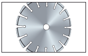 A. Loss of Tension / Blade Distortion
Possible Causes
1. Saw is not properly aligned.
2. Blade/bond is too hard for the material being cut leading to excessive stress.
3. Attempt is being made not to cut in a straight line.
4. Material has slipped and caused blade to buckle.
5. Fixing flanges are not of correct size, balanced or aligned.
6. Diamond Blade not properly fitted to spindle.
7. Excessive or uneven wear at blade circumference puts pressure on the core.
8. Steel core overheating or not sufficiently water-cooled.
9. Excessive speed/rpm being attempted.
10. Pre-cut blade has not been used to prepare for deeper cuts.
11. Blade damaged or dropped during transport or handling.
Corrective Measures
1. Realign.
2. Select correct blade.
3. Ensure cutting is straight and blade at 180º to material being cut.
4. Ensure that material to be cut is firm and stable.
5. Ensure that flanges are of correct size, uniformly fitted and adequately (but not excessively) tightened.
6. Ensure blade is fitted to spindle without excessive play or tightness.
7. Check wear patterns regularly and replace/repair as necessary.
8. Check cooling system and water distribution.
9. Reduce speed.
10. Use pre-cut blade whenever possible or appropriate.
11. Check blades carefully before use. Replace/repair as necessary.
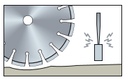 B. Loss of Tension / Diamond Blade Distortion
This describes the situation when the steel cores/centres wear more rapidly than the segments on the circumference. It can lead very rapidly to segment loss.
Possible Causes
1. Attempting to cut too fast or too deeply in one pass.
2. Bond too hard – can lead to ‘pounding’.
3. Excessive feed pressure.
4. Blade spinning freely on spindle.
5. Shaft worn, grooved or damaged.
6. Water pressure too low, flow insufficient or unevenly distributed.
7. Blade cut too deep – no coolant reaching cutting edge.
Corrective Measures
1. Do not be too ambitious in depth of cut which is possible at one pass. Multiple shallow cuts may take longer, but will protect the equipment and are quicker in the long run.
2. Select correct blade for material to be cut.
3. Reduce feed pressure.
4. Correct fit of blade to spindle.
5. Replace or repair.
6. Check cooling system and water distribution.
7. Reduce depth of cut. See 1 above
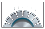 C. Overheating
This can easily be detected by noting a black or blueish discoloration of the steel core.This can easily be detected by noting a black or blueish discoloration of the steel core.
Possible Causes
1. Attempting to cut too fast or too deeply in one pass.
2. Bond too hard – can lead to ‘pounding’.
3. Excessive feed pressure.
4. Blade spinning freely on spindle.
5. Shaft worn, grooved or damaged.
6. Water pressure too low, flow insufficient or unevenly distributed.
7. Blade cut too deep – no coolant reaching cutting edge.
Corrective Measures
1. Do not be too ambitious in depth of cut which is possible at one pass. Multiple shallow cuts may take longer, but will protect the equipment and are quicker in the long run.
2. Select correct Diamond Blade for material to be cut.
3. Reduce feed pressure.
4. Correct fit of blade to spindle.
5. Replace or repair.
6. Check cooling system and water distribution.
7. Reduce depth of cut. See 1 above
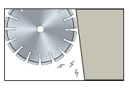 D. Diamond Blade Will Not Cut
Possible Causes
1. Bond too hard / blade being used on wrong material, leading to bluntness
– blade becomes ‘glazed’.
2. Machine power inadequate for task (wrong motor, voltage or belt tightness).
3. Incorrect or altered direction of cut, leading to jamming.
4. Segments missing or badly worn.
5. Segments have become smooth and are not cutting, even though not fully worn.
6. Excessive coolant causing blade to float or aquaplane.
7. Excessive motion or play between the carriage guides.
8. Insufficient feed pressure / rate.
9. Freeback has been reached.
10. Incorrect direction of rotation.
11. Water pressure too low, flow insufficient or unevenly distributed
Corrective Measures
1. Select correct blade to achieve the correct bond. Open-up glazed segments by working briefly on very abrasive material.
2. Select correct motor capacity, voltage and check belt tightness.
3. Realign direction / angle of cut.
4. Repair blade and replace segments if possible. Otherwise, replace blade.
5. Open up glazed segments by working briefly on very abrasive material.
6. Reduce flow of coolant.
7. Realign and tighten carriage guides.
8. Increase feed pressure / rate.
9. Blade is worn out, replace blade.
10. Correct direction of rotation.
11. Check cooling system and water distribution.
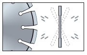 E. Diamond Blade Wobble / Flutter
Possible Causes
1 – Flexing due to excessive feed or rotational speed.
2 – Flanges incorrectly fitted/tightened/ balanced (could also be due to debris being trapped between flange and blade – check for this).
3 – Incorrect mounting of blade on shaft – problem compounded when flanges are tightened.
4 – Shaft bearing worn or damaged.
5 – Blade tension does not match cutting speed.
6 – Blade tension lost, leading to flutter and further distortion when speed increased.
Corrective Measures
1 – Reduce speed and monitor performance.
2 – Correct flange fittings and remove any debris trapped between flange and blade.
3 – Mount blade correctly. Do not tighten flanges excessively.
4 – Replace or repair.
5 – Re-tension blade in balance with cutting speed.
6 – Recalibrate blade tension.
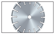 F. Diamond Blade Distortion / Out of Round / Damage to Arbor or Bore
(Check against the causes listed under E) above, and also consider the following additional possibilities).
Possible Causes
1 – Bond too hard, causing diamonds to become prematurely worn and smooth. This leads to ‘pounding’ and loss of blade shape.
2 – Arbor hole does not match shaft diameter or has become worn.
3 – Drive pin not fitted to rear flange or properly located in its retaining hole.
4 – Motor not correctly tuned.
5 – Blade spinning on spindle shaft or running loose.
6 – Blade spindle grooved or damaged, leading to eccentric running.
7 – Inadequate lubrication to spindle bearings (especially when sawing concrete).
Corrective Measures
1 – Select correct blade for the material being cut.
2 – Rematch arbor and shaft. Repair or replace arbor if worn.
3 – Ensure that all drive pins are correctly located in their mounting holes.
4 – Retune machine motor.
5 – Check that blade core fits snugly onto its drive shaft.
6 – Replace or repair damaged blade spindle.
7 – Improve lubrication to bearings.
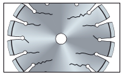 G. Diamond Blade Cracking to the Core
Possible Causes
1 – Bond too hard.
2 – Excessive feed pressure or rotational speed.
3 – Core loses tension because of excessive heat load (see C on previous page).
4- Core distorted through incorrect line of cut.
5 – Damaged bearing or faulty mounting.
6 – Blade twists or jams in cut.
Corrective Measures
1 – Select correct blade for material to be cut.
2 – Reduce feed pressure and/or speed.
3 – Reduce speed and check coolant supply.
4 – Correct line of cut.
5 – Replace or repair bearing / mounting.
6 – Remove blade, allow to cool and check coolant/lubrication.
2. Diamond Segment Faults
 A. Segments ‘Glazed’ and Will Not Cut
Possible Causes
1. Line of cut is not straight.
2. Bond too hard – can lead to pounding and fracture of segments.
3. Failure to notice segment cracks.
4. Excessive feed pressure.
5. Flanges worn / insufficiently or unevenly tightened.
6. Out-of-round wear pattern.
7. Material slips during cutting.
8. Eccentric wear pattern on blade core.
9. Segment damaged or loosened during transit.
10. ‘Undercutting’.
Corrective Measures
1. Select correct blade for material bond.
2. Open up glazed segments by working briefly on very abrasive material.
3. Increase feed pressure.
4. Freeback is not a fault. Select new blade.
5. Increase power to blade.
6. Correct direction of rotation.
7. Reduce speed of rotation.
8. Increase water pressure.
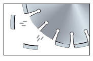 B. Segment Loss
Possible Causes
1. Line of cut is not straight.
2. Bond too hard – can lead to pounding and fracture of segments.
3. Failure to notice segment cracks.
4. Excessive feed pressure.
5. Flanges worn / insufficiently or unevenly tightened.
6. Out-of-round wear pattern.
7. Material slips during cutting.
8. Eccentric wear pattern on blade core.
9. Segment damaged or loosened during transit.
10. ‘Undercutting’.
Corrective Measures
1. Improve straightness of cut.
2. Select blade and bond suitable for the material to be cut.
3. Check appearance of segments regularly and replace/repair when necessary.
4. Reduce feed pressure.
5. Ensure flanges of the correct size, balance and tightness during operation.
6. Check spindle and core correctly centred.
7. Ensure material is held rigid during cutting.
8. Check spindle and core correctly centred. Replace spindle if necessary and/or fit new bearings.
9. Always check blades and segments before usage.
10. Reduce depth of cut to minimum necessary to prevent contact with abrasive sub-base (protective segments may be used to protect the blade in extreme cases).
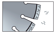 C. Segment Cracks
Possible Causes
1. Arbor hole does not match shaft diameter.
2. Excessive feed pressure.
3. Rotation speed too high.
4. Worn, grooved or damaged shaft.
5. Excessive machine vibration or instability.
6. Problems with coolant supply
Corrective Measures
1. Arbor hole does not match shaft diameter.
2. Excessive feed pressure.
3. Rotation speed too high.
4. Worn, grooved or damaged shaft.
5. Excessive machine vibration or instability.
6. Problems with coolant supply
 D. Excessive Wear to Segments
Possible Causes
1 – Incorrect match of material and blade – bond too soft.
2 – Excessive feed pressure causing blade to flex.
3 – Misalignment of blade and machine.
4 – Out-of-round wear pattern.
5 – Rotation speed too low or loose/slipping drive belts.
6 – Worn, grooved or damaged shaft.
7 – Excessive machine vibration or instability.
8 – Blade not at 180º to material being cut.
Corrective Measures
1 – Select correct blade with harder bond.
2 – Reduce feed pressure.
3 – Realign blade and machine.
4 – Check spindle and core correctly centred. Replace spindle if necessary and/or fit new bearings.
5 – Increase rotation speed. Check and tighten drive belts.
6 – Repair or replace shaft.
7 – Ensure stability of machine. Operate at low speed initially and monitor performance.
8 – Ensure blade cuts directly onto material.
 E. Uneven Segment Wear
Possible Causes
1 – Excessive feed pressure.
2 – Flanges not holding blade properly.
3 – Misalignment of blade and shaft.
4 – Worn, grooved or damaged shaft.
5 – Blade spinning on spindle – drive pin not engaged.
6 – Water pressure too low, flow insufficient or unevenly distributed.
Corrective Measures
1 – Adjust feed pressure.
2 – Ensure flanges of the correct size, balance and tightness during operation.
3 – Realign blade and shaft.
4 – Repair or replace shaft.
5 – Ensure that all drive pins are correctly located in their mounting holes.
6 – Check cooling system and water distribution.

